earthing and grounding system

Earthing system(uk) or grounding system(us) increases the conductivity of the ground by providing the least resistance to the ground surface. This installation method is done in an industrial area, switchyard, substations, Power station etc.
 
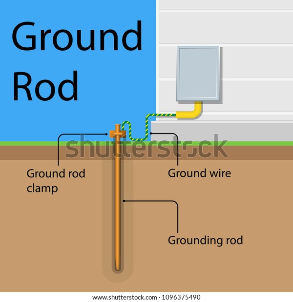
How earthing is done?

Conductors are buried inside the earth and filled with some conducting material.  
 
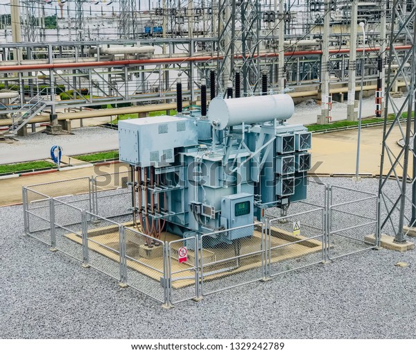
 Every switchyard should bear the earthing system or earthing grid installation. Earthing grid provides personnel safety and protects the equipment from fault current or short circuit current by allowing fault current into the ground.
 
 Three phase Big Electric Power high volt transformer in substation 

How the earthing system provides personnel safety?

At switchyard two types of potential or voltage can affect the person due to overcurrent and over voltage,but if switchyard consists of earhing it provides least resistance allows overcurrent into the ground.
 

 Step potential.

At the time of earth fault or short circuit current,
potential or voltage develop between two foot of the body.(Eg..if 1500A flow into 5 Ohm ground impedence it 7500v is develop between two foot) 

 Touch Potential. 

  In this situation  potential or voltage,develop between electrical equipment (which carry fault current)and person's hands(who touches that equipment).
 
To  avoid these two conditions,earthing grid are provided at each switchyard.It act as a earth mat for whole substation or switchyard.
 
Earthing On Electrical Equipment.
All the body of electrical equipment such as transformer, circuit breaker, Instrument transformer, Panel is commonly connected on earth-grid or earth rod through single bus conductor.

Electric power distribution leak house surge strike device finials shock panel phase protect AC pole wire home plants tower repair safety cable station service industry neutral connect generation

Neutral earthing system

If neutral of the electrical equipment such Power transformer(dyn11)is connected on earth rod then it is called neutral-earthing system.

Types are 
1.Solid grounding.
 
2.Resistance grounding.
 
3.Reactance grounding.
 
4.Peterson coil grounding

  DESIGN CONSIDERATION.

 Earthing system plays an important role in the construction of switchyard, power system, Industry because of that reason IEEE standard-80, IS-3043 and IEC standard-60364 gave standardized guidelines to follow while designing earth grid.

According to Ieee standard some of the input required to design.
 
1. Up-normal current & duration.
 
2. Ground current & fault clearing time.
 
3. Soil resistivity.
 
4.Area of switchyard. 
 
 Three main aspects should be considered while designing the earth system.

I)  Conductor cross sectional area(sqmm) should  withstand faulty current and over   voltage.

II)   Grid sizing and spacing should be uniform.

III) Step potential and touch potential.

what is the coloumbs law?coloumbs law equation explaination,mathematical problems on coloumbs law.

Do you want to know coloumbs law of electrostatic?

 Coloumbs first law, 
i)Same charges repel to each other.
ii)Opposite charges attract to each other.
 
Coloumbs second law ,
Force between two charges is directly proportional to 
 
i) Multiplication of two charges.
ii)Inverse square of the distance. 

Elaborating coloulmbs second law. 
 
Consider two charges Q1 and Q2. 
 
ie, F ∝Q1*Q2      ---------->second law (i).
F∝1/d^2 ---------------≻second law(ii).
F∝ Q1Q2/d^2

F=k. Q1Q2 /d^2
 
K  is constant,so its value is 
 

 1➗4ㄫεoεr


εo=absolute permittivity of vaccum or air
=8.854*10^-12 farad/meter
     
 
εr=relative permittivity of the medium.
 (value is 1 for air or vaccum medi)
 
F=q1q2 ➗(4πεoεr)
         
F= q1q2 ➗(4π*8.854*10^-12*εr*d^2)

while elaborating the condition,we get
 
F=(9*10^9*Q1Q2)/(d2)

myelectricalscience-Simple explanation on electric current,definition of Electro static,electric field,electric flux,electric flux density.electric field intensity,electrical potential. Formula for electric flux symbol of electric flux,formula for electric field intensity,definition for emf

ELECTROSTATIC

First of all,I clear you what is static electricity?
Whenever there is a frictional force between two surface of the body that frictional force is converted into ''static electricity'' or ''Electrostatics".

Why electrostatic or static electricity is produced?

when two surface of body contact and slides on each other then "charges" of this two body transfer to one another. 
Example-Glass rod and silk cloth experiments, Bending water,Chair and towel experiment etc. proves charges transfering.

what is Charges?

In an atom there are three particles Proton,Electron,and Neutron.symbol is "q".
Proton is a positively charged sub-atomic particle.
Electron is a negatively charged sub-atomic particle.
Neutron is in neutral.No charges are present in this sub-atomic particle.

What is an electric field?

Force excerted by charge(+ve or -ve) on a space is called as electric field.It will not visible but it can represented by graphical lines in theoretically.
Illustration vector icon of electric field around negative electric sphere charge conductor. Physics science experiment.f
The lines which represent electric field are called "Electric lines of force".

What is an electric field intensity(E)?
A force execerted by a single positive charge at a point is called ''electric field intensity''.

E=F\Q  
force by charge

E=electric field intensity.
F=force in newtons acting on couloumbs.
Q=charge in couloumbs.

What is an Electric flux?

The total lines that surrounds a particular charge is said to be an "electric flux"Electric flux measures the "electric field".Its unit is couloumb(c). Symbol for elctric flux(ϕ).

what is an Electric Flux Density(D)?
Electric flux density is equal to Electric flux per unit
area at an electric field.
                           
D= ϕ /A coloumb\m^2

What is an electic potential?
This is a type of work which moves a one coloumb 
of charge from infinity distance to the electric field,
that work is called ''Electric potential''.


p=E
ϕ


Types of Electric cable basics|Types of cable for fresher|cable basic Interview topic |simple explanation electrical cable| main purpose of cable| |Usage and application of electric cables.

Electric Power Cable

 Main purpose of electric cable is used to transmit the electrical energy at high voltage.Cable may transmit and Receieve power through, Overhead and Underground cables. Cable conductor is surrounded by insultor material (xlpe,epr,pvc,etc.).Most of the cable manufacturer prefer Xlpe insulating material.According to flow of voltage, cable can be broadly classified into LV cable,MV cable,HV cable,EHV cable,and UHV cable.
Installation method
   Electric cable may be install permanently on conduit buried,cable trays,cable trench,etc

The cables are used for transmission of electrical energy at high voltage. Hence testing of  Power cables are also must required,standard IEC 60502-1 also explain's cable construction,dimension and Testing requirement for electric cable.


myectricalscience,AC Lv cable sizing for ACDB equipments electrical cable sizing,lv cable sizing calculation--cable engineering sizing calculation-myelectricalscience.

Hello,friends I am going to explain a simple steps on calculating cable size.  
Cable sizing is very important for substation designing, Correct sizing of cable protect the cable from burningshort-circuit current, voltage drop and other abnormal condition.Cable sizing is measured on sq mm. 

Cable should statify two condition
1. Ampacity(continuous current carrying capacity of conductor)
2.voltage drop must be within 5%(Volt difference b\t sending end and  receiving end)                                                                     
 Select the type of cable or cable data,
1.Conductor(cu orAl)
2.Insulator(pvc,xlpe,epr etc.)
3.No of core(SINGLE OR MULTI-CORE).
 
NOTE: Normally xlpe insulation is taken for modern substation. so i am selecting copper, xlpe and multi-core.

Now we going to do the cable sizing calculation side, believe me this going to be easy for you. 

STEP-1,

COLLECT LOAD DATA.

EXAMPLE-Consider Heat ventilation air condition (hvac unit-1) on ACDB requires operating power of 15000w connected on 1-PHASE station service transformer(8.4kv\240v) Now through station service trafo data we came to know voltage is 240v. power factor is 0.85(active power). 

we all know the formula P=V*I*COS(fi) 

Find VA rating for load; p/cos(fi)  
                
Find full load current(I)=va/(v*qty of load) 
  
Here Qty of HVAC load is 1 so voltage is multiplied with 1 if load qty is 2 then multiply by 2.
 
Now find the tripping current and breaker rating ie,multiply full load current into 120% 
VA rating              ie, 15000/0.85         
 
= 17647.5 VA   
 Full load current  ie, 17647/(240*1)   
 
= 73.5291A.
Tripping current    ie,73.5291*1.2       
     =88.235A 
                                                                        
  Selected breaker rating is 90A. 

 STEP-2,

FIND THE TOTAL CORRECTION FACTOR OR DERATING FACTOR.

Selecting "derating factor" is based on where the cable is going to install(eg. outside building or inside building,cable trench etc,conduit buried).This may be choose with help of "single line diagram" by seeing location of equipment. 
Now you select where the cable is going to install and check  your selection on "installation method" with help of cable manufacturer data.

EXAMPLE TABLE(Real manufacturer has lot of installation method)
derating factor manufacturer table.
case noinstall-method

no of run
 
max sq mm
 no of cores

tot,derating factor

     1trench,outside building      1upto 400  20.721
    2conduid buried      425to150 40.647
 eg:cable manufacturer table list shown.
 
Total correction factor depends on soil temperature,air temperature,soil resistivity,and air resistivity. that will provide by manufacturer.
 

Example:If I am going to select "Conduid buried" method on flat condition then cable size is upto"16sqmm" and total derating factor is 0.647.

Uprated load current should be found by the formula,
                                 
 Uprated load current  
breaker tripping current \ total correction factor
                                                    
                               = 90 \ 0.647
               
            Uprated load current    =139.14 A  

With the help cable manufacturer data we have to check the Ampacity.
Ampacity, should higher than uprated load current.

xlpe,cu,unarmoured cable
 
Cross section
sqmm
@flat condition
Cur-1-tr-flat condition (Ampacity) flow
Cur-1@Pipe Ampsflow (ampacity)
 Rac -90deg  celc  Xac-90deg celc  Rdcouter dia
2C*25
118
900.9270.12410.727  22.4  
2C*351421070.6690.1184 0.524 24.6
2C*501751290.4940.1115 0.387 -
 
According to manufacturer data I've selected "2C*35mm^2"Ampacity of cable is "142 A" 

STEP-3

VOLTAGE DROP must within 5% for total connected load.

now here only single load so below 1% is required. 
 
For single phase  Vd=2IZ     
 
For 3Phase Vd=√3IZ
         I=full load current
         Z=Impedence  (Rx*cos(fi)+Xac*sin(fi))
         2-phase and neutral.(1 phase)
 
 
 Note cos(fi) sin(fi)

 0.85 0.53


Vd=2I*L((Racc*cos(fi)+Xac*sin(fi))/(1000*no of runs) 
 
             
L     = length in meter
Rac =Resistance of selected cable.
Xac =Reactance of selected cable
 
 
Vd =73.529*20(0.669*0.85+0.1184*0.53)/(1000*1)
 
Vd =0.928v   
 
         
To find voltage drop in percentage %
  =(Vd / operating voltage*100) 
 
   
                        % of voltage drop is 0.386

                  If you have any doubt please ask in comment section I am ready to clear your doubt